Design and building of a Tesla coil capable of producing 30cm arcs. It is based on two RLC resonnant circuits.
Tesla Coil Pt.1, DIY
Introduction
Who has never dreamt of being a Greek god, even for a moment? Today, I'll tell you how I actually fulfilled that dream. Sure, I already look like Apollo, but I also wanted the power of Zeus. In this quest, I decided to build an iconic machine capable of generating hundreds of thousands of volts; the famous Tesla Coil! Here is how I did it...
How it works
The Tesla Coil (invented by... Tesla, I guess) is a high-voltage generator based on some fascinating physics principles, resonnance. On the practical side, it is also surprisingly easy to build, as it doesn't require any fancy electronics or specialized tools. Theoretically, it relies only on two coupled RLC circuits (the kind that overwhelms first-year STEM students).
Physical Principles
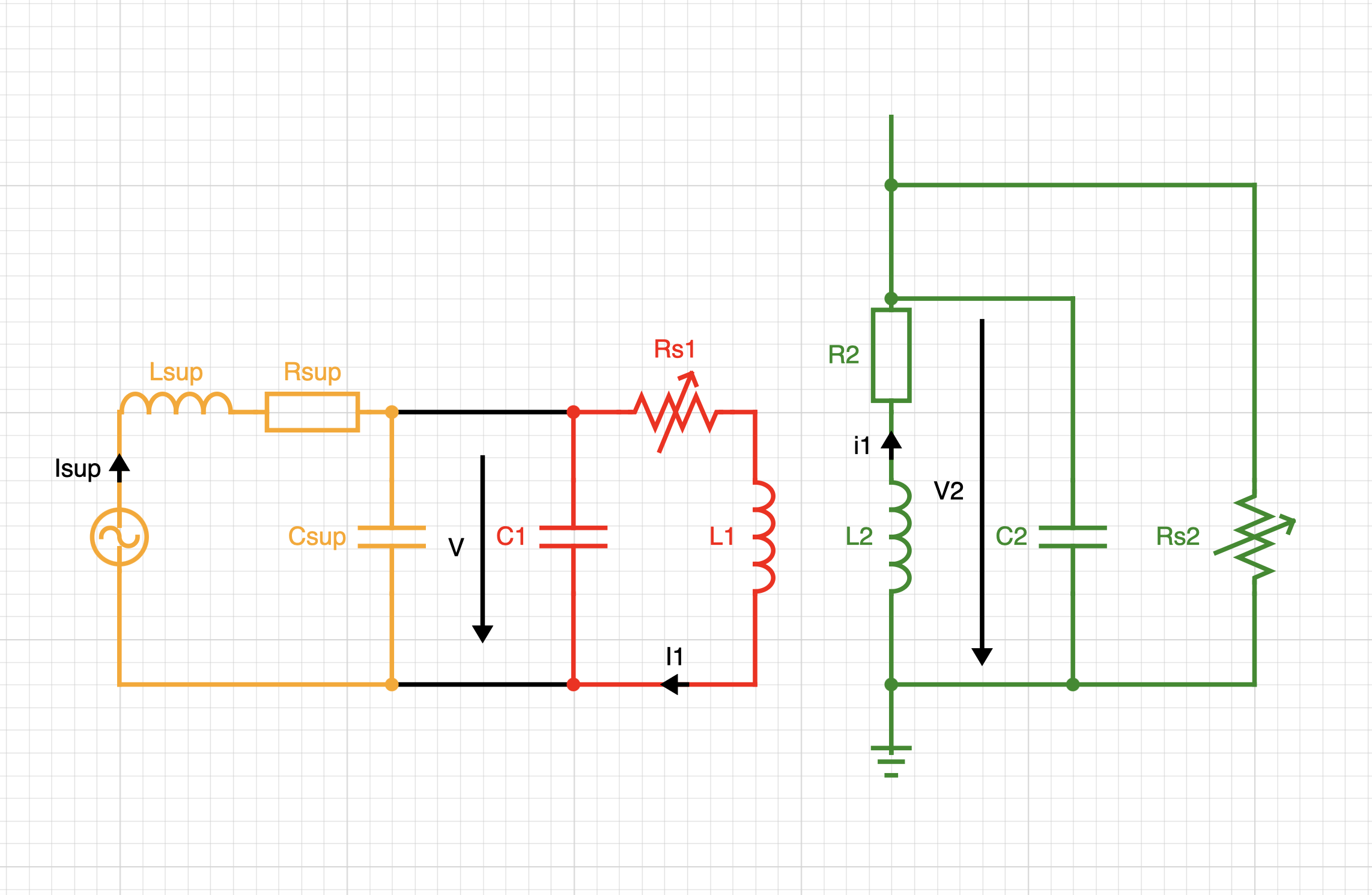
Circuit
The core idea is to accumulate energy in a large capacitor () and discharge it through a spark gap () into an inductor (). Together, these form the primary circuit. The secondary circuit consists of a large inductor (, wound with thousands of turns) that picks up energy from the primary and multiplies the output voltage. This inductor is grounded on one end and connected at the other to a large spherical or toroidal electrode. This electrode increases the parasitic capacitance at the top of the coil, introducing a very useful capacitance . These form the secondary circuit.
Combined with a power supply, these elements make up the complete theoretical foundation of the Tesla Coil. The two key design requirements are: matching the resonant frequencies of both RLC circuits (typically around kHz), and ensuring to achieve significant voltage multiplication.
Operating Cycle
-
The transformer charges . For simplicity, the AC power supply can be treated as effectively DC relative to the Tesla Coil's resonant frequency ( Hz vs. kHz).
-
Once the voltage across is sufficient to trigger a dielectric breakdown at the spark gap , the circuit closes and current flows from the capacitor into the inductor.
-
This current oscillates between the capacitor and the inductor at around kHz. This frequency is determined by the classic formula :
-
The current through the primary inductor generates a magnetic field whose variations induce a voltage across the secondary inductor .
-
This voltage drives a current oscillating between the secondary inductor and the parasitic capacitance ; at the same frequency as the primary, if properly tuned.
-
Over several oscillations, the secondary circuit draws energy from the primary, causing the secondary voltage to build up rapidly.
-
Once this voltage reaches the breakdown threshold, the top electrode discharges itself through arcs of hundreds of thousands of volts ().
-
This discharge dissipates energy from the system and oscillations cease, until the power supply recharges , typically at around the supply frequency.
Analogy: You can imagine a child on a swing (the secondary circuit). Another person (the primary circuit), powered by an energy source (the supply), gives small pushes at just the right timing. Each push adds a bit more energy, so the swing goes higher and higher over successive oscillations, just like the voltage builds up in the secondary.
Building Process
Warning: This machine is not a toy. The voltages involved (tens of thousands of volts) are lethal if not handled with the utmost care. Looking back, I built this at a fairly young age and with insufficient precautions — I would be far more rigorous today. If you intend to replicate this, please document yourself seriously on high-voltage safety before starting. By the way, this video is excellent to better understand the danger ( Is it the volts or amps that kill? - by Styropyro)
Materials
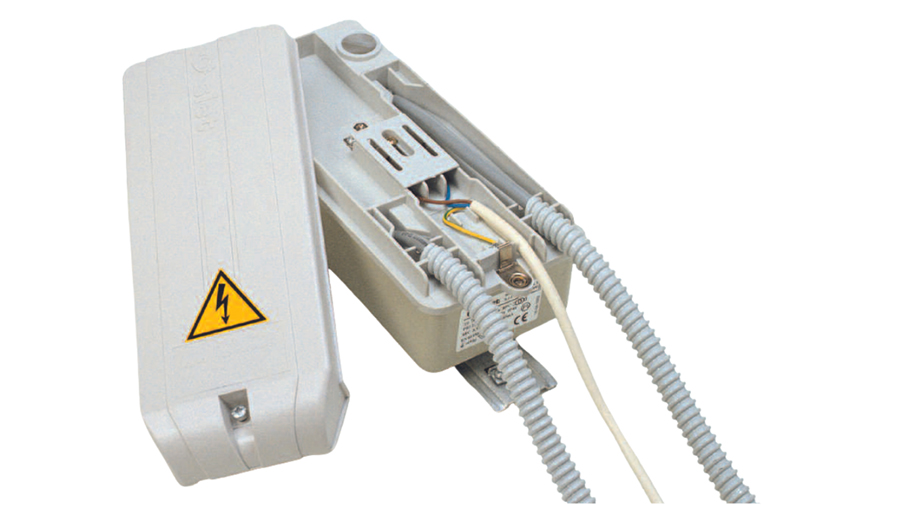
Power Supply
- A Neon Sign Transformer (NST) — the more powerful the better. In my case I used an 8 kV model.
- A 220V cable with plug
- A 220V switch
- A circuit breaker
- A high-frequency filter
- An electrical enclosure box
Primary Circuit
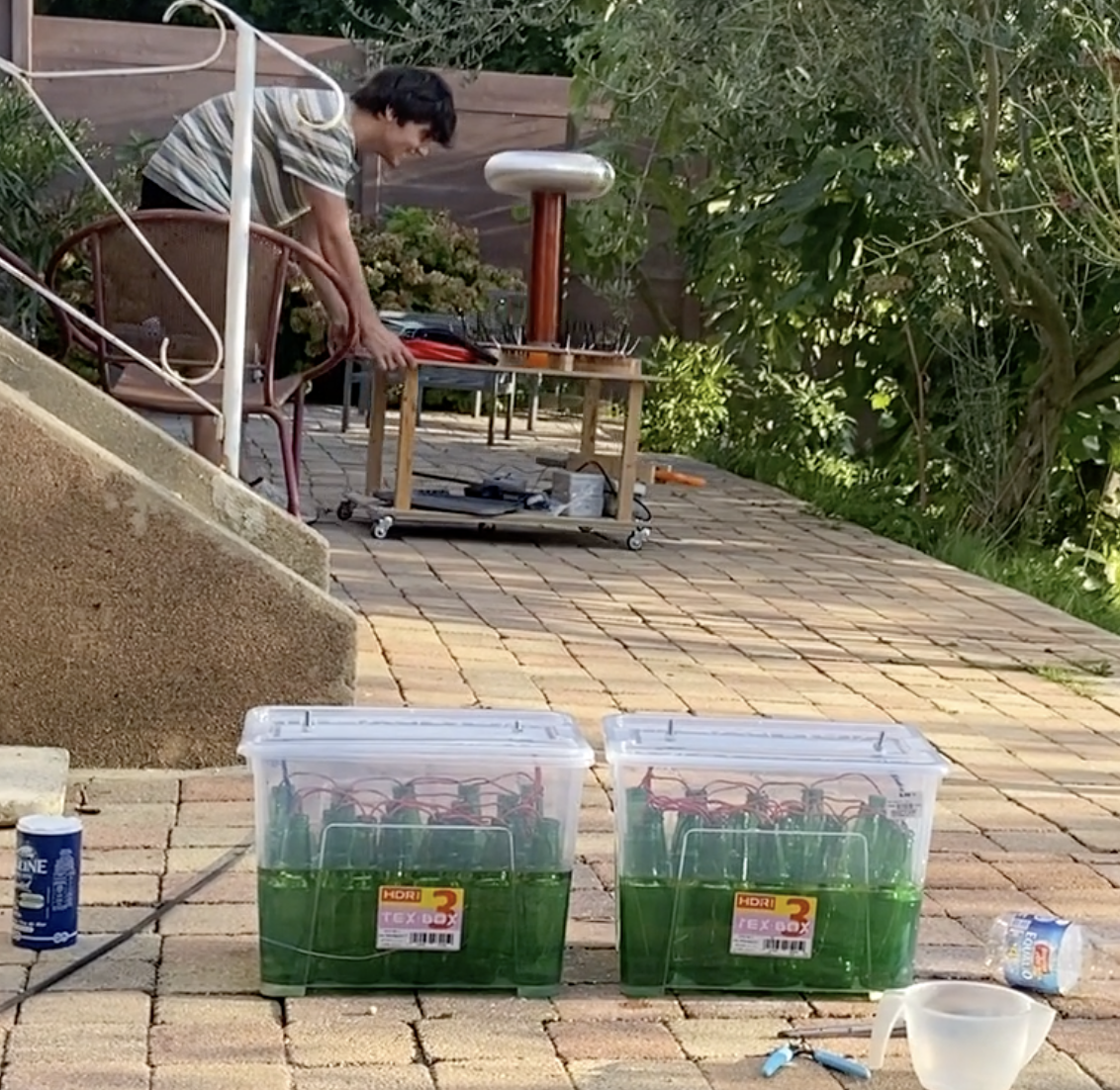
- 10 meters of 14–18mm ⌀ copper pipe for (tube is fine since skin effect is strong)
- ~40 glass beer bottles
- Saturated salt water
- 1L of mineral oil
- A large plastic container
- A crocodile clip
- A spark gap with carbon/copper/stainless steel electrodes, adjustable via a bolt system
Secondary Circuit
- 500–1000 m of enameled copper wire, 0.3–0.4 mm ⌀
- A 50 cm section of PVC pipe, 10 cm ⌀
- ~12 cm ⌀ of stretchable aluminum duct + conductive tape
- ~30 cm metallic rod, for grounding
General Hardware
- Cable ties
- 2 wooden boards
- 4 omnidirectional wheels
- Basic soldering equipment
- Some solid copper wire, 1–2 mm ⌀
- Some screws, bolts etc
Building
Power Supply
Wire the plug, circuit breaker, and switch in series, then connect the phase, neutral, and earth correctly to the NST input terminals. Mount the circuit breaker and switch inside the electrical enclosure, make it fancy, be creative !
Primary Circuit
For this class of Tesla Coil, a primary capacitance of a few nF is typical. You can buy one (MMC capacitor bank, quite expensive...), but you can also build it yourself! The idea is to place glass bottles inside a plastic container, then fill each bottle, as well as the space around them, with saturated salt water up to the neck. Add 1–2 cm of mineral oil on top to improve the insulation between the inside and outside of the bottles. Finally, connect all the bottle interiors together, and place an electrode on the outside — these form the two terminals of your primary capacitor.
Note: Let the capacitor rest for at least one hour before measuring its capacitance. The insulation is not fully effective before this settling period, which significantly affects the measured value.
To estimate the capacitance for a given number of bottles before building, use the standard parallel-plate formula:
where is the dielectric constant of glass, is the contact surface area between the bottle wall and water, and is the wall thickness of the bottle. In my case, 38 bottles yielded a 20 nF capacitor.
You can already connect the power supply output to the two terminals of the capacitor.
For the spark gap, many designs exist, but a simple pair of adjustable electrodes is sufficient here. It is important to allow airflow between the electrodes to help the gap quench properly after each discharge.
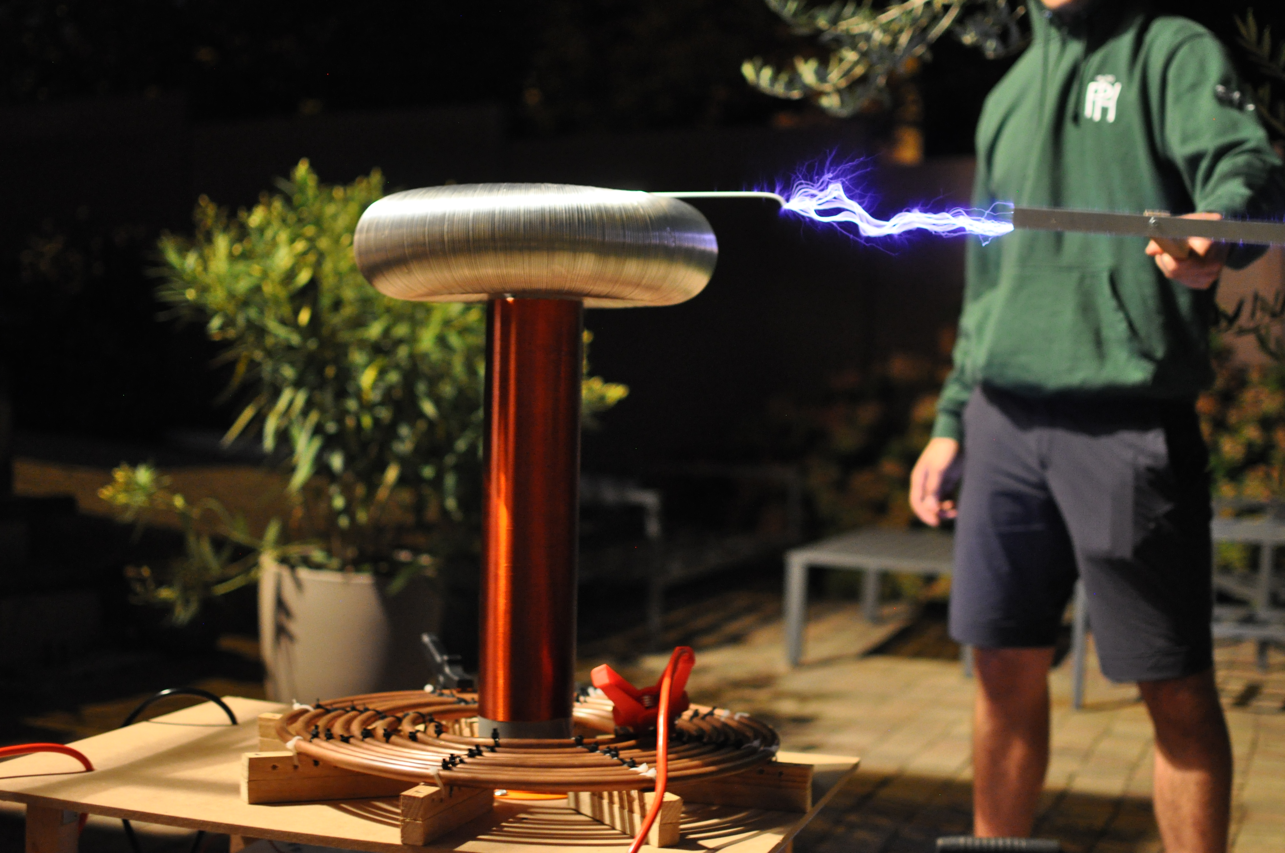
For the primary inductor, bend the copper pipe into a flat spiral of approximately 10 turns.
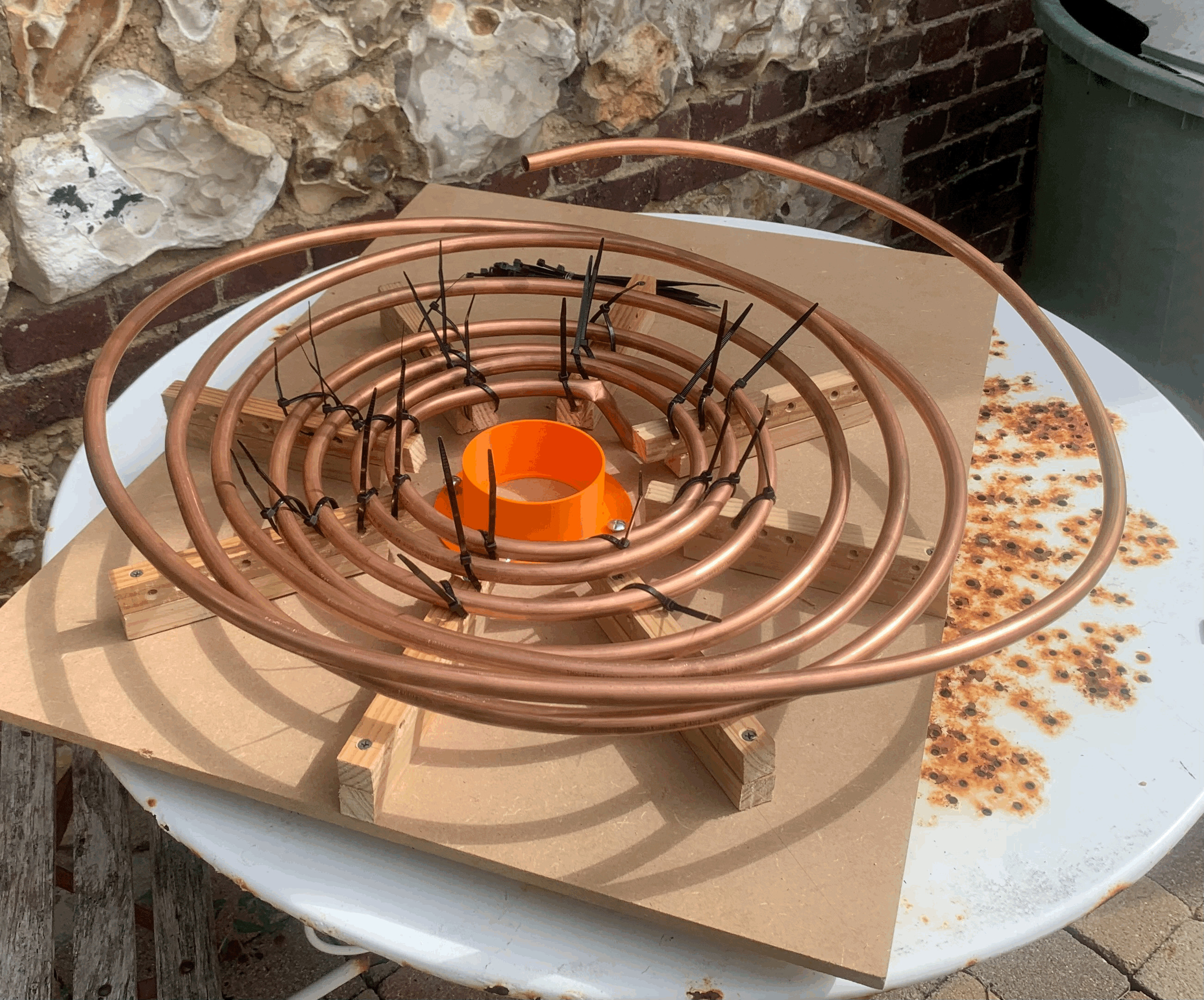
Connect the center of the spiral to one terminal of the capacitor. Connect the other terminal of the capacitor to the spark gap and a crocodile clip. Finally, connect the crocodile clip to the other end of the coil. This clip allows you to tune the primary circuit by adjusting the effective number of turns.
The power supply, spark gap, and primary capacitor sit on the lower shelf of a small wooden trolley. The primary coil is mounted on the upper shelf.
Secondary Circuit
Wind a large number of turns of copper wire around the PVC pipe — 1600 turns in my case. Form a toroid from the aluminum duct and solder it to the top of the coil. The bottom terminal of the secondary coil must be grounded using the metallic rod. Position the secondary coil at the center of the primary spiral.
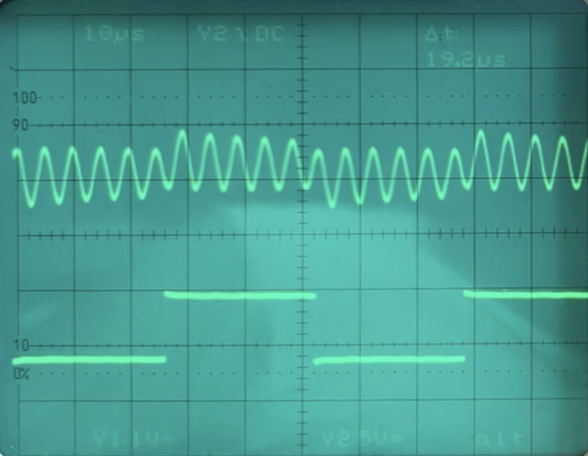
To measure the resonance frequency of the secondary, connect a function generator set to a few tens of kHz and a few volts between the bottom of the coil and ground. Then use an oscilloscope to measure the voltage between ground and the air near the toroidal electrode, it will oscillate at the resonant frequency.
And voilà, you have a working Tesla Coil!
Taaaadam
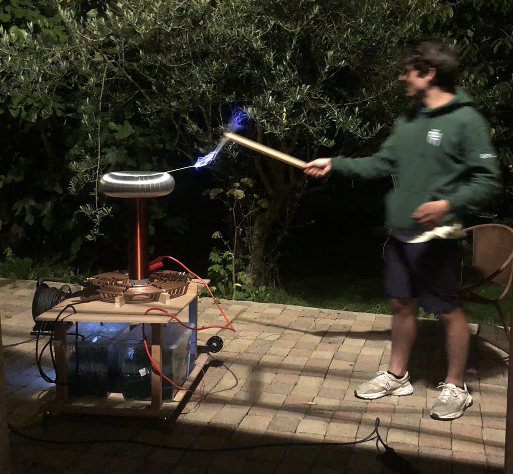
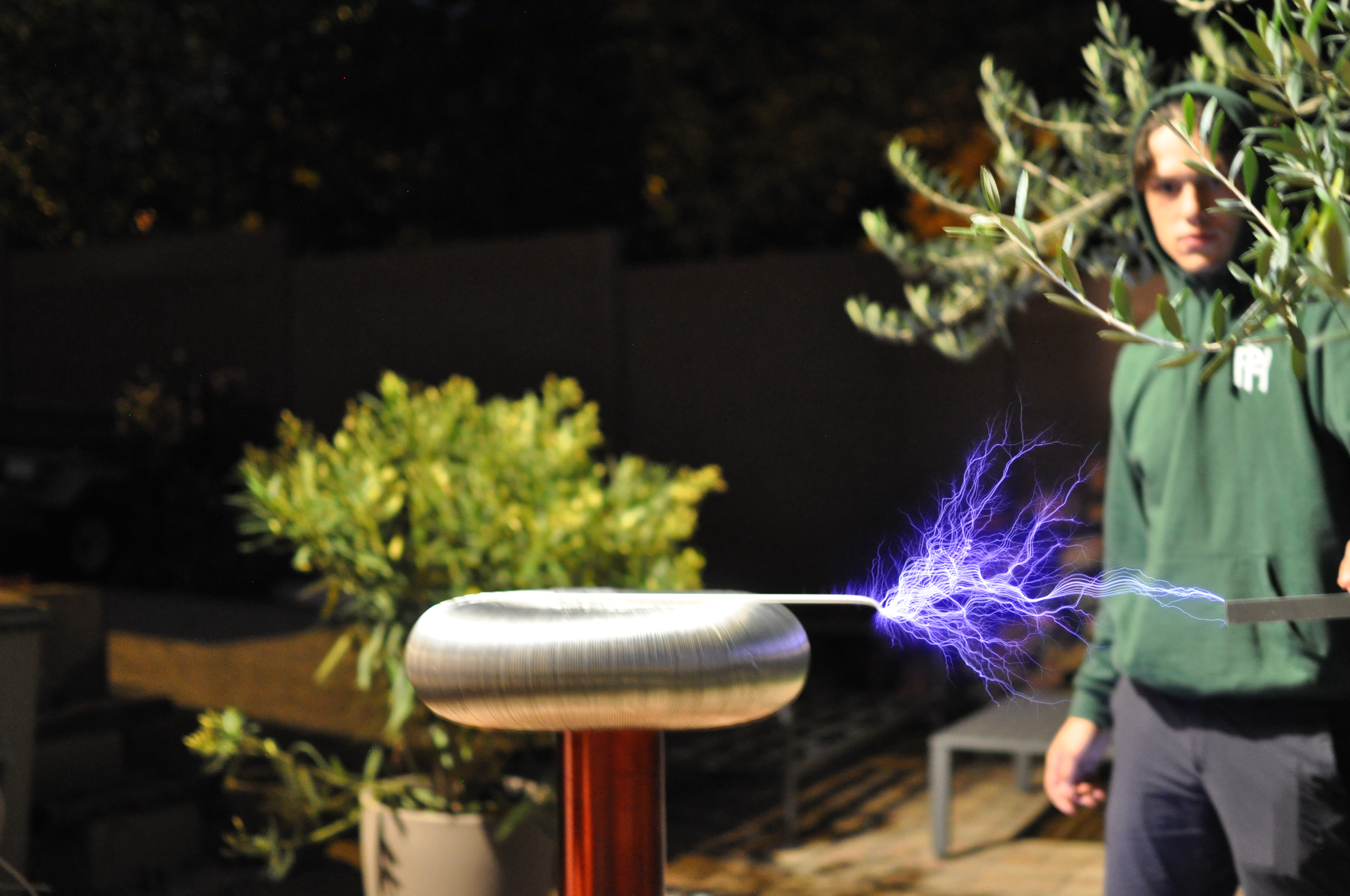
Finally, here are some images and a video of my Tesla Coil running ! This was for me, as a young first year physics student, a big accomplishment. This Tesla Coil now finishes its days at the university of Le Havre, my hometown.
Outlooks
- Better safety measures
- Better isolation, at some point the coil interfered with the washing machine and fried its display...
- Replace the homemade bottle capacitor with a proper MMC capacitor bank (a bit pricey...)
- Upgrade to a more advanced circuit (Solid State, Dual Resonant,...)